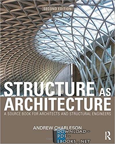
❞ كتاب دورة الشوب درونج الانشائى    Structure As Architectrue ❝

❞ كتاب دورة الشوب درونج الانشائى Structure As Architectrue ❝

دورة الشوب درونج الانشائى

STRUCTURE AS ARCHITECTURE
LOUISE PEDERSEN and JONAS TÄLJSTEN


v
Index
Preface.................................................................................................................. i
Abstract..............................................................................................................iii
1
Introduction ................................................................................................. 1
1.1 Back
ground
.................................................................................................................
1
1.2 Objective ..................................................................................................................
... 1
1.3 Limitations................................................................................................................
... 2
1.4 Outline
of thesis ..........................................................................................................
2
2
The collaboration......................................................................................... 5
2.1
A structural engineer
’s way of working ..................................................................... 5
2.1.1
The finite element method and programs used................................................... 5
2.2 An architect’s
way of working.................................................................................... 6
2.3
Communication between architects and engineers..................................................... 7
2.3.1
Formfinding according to
Popovic Larsen
and Ty
as ......................................... 8
3
The architect competition ......................................................................... 13
3.1
Our process in the museum project........................................................................... 13
3.2 Formfinding process.................................................................................................. 14
3.2.1
The outside form ............................................................................................... 14
3.2.2 The supports ...................................................................................................... 15
3.2.3 The curves ......................................................................................................... 17
3.2.4 The middle......................................................................................................... 21
3.2.5 Under ground
and wind
ows
..............................................................................
24
4
Optimizing the building ............................................................................ 27
4.1 Different bounda
ry conditions .................................................................................. 27
4.1.1 A general beam ................................................................................................. 27
4.1.2
The Art Museum as a model in Abaqus ........................................................... 32
4.1.3
Fixed supported building .................................................................................. 33
4.1.4 Roller sup
ported buil
ding ................................................................................. 36
4.1.5
Roller supported building
with a column in
the middle ................................... 38
4.1.6
Building supported by
glass walls an
d cable
s ..................................................
41
4.1.7
Comparing the different ways
in supporting a building ................................... 45
4.2
Better material efficiency with lower density........................................................... 47
4.2.1 Concrete she
ll with holes .................................................................................. 47
4.2.2 A general beam ................................................................................................. 48
4.2.3
How to make calcul
ations with holes ............................................................... 49
4.2.4
A model with holes only in the areas with low stress ...................................... 51
4.2.5
A model with holes only in the areas with high deformation .......................... 52
4.2.6
A model with holes balanced over the whole body.......................................... 53
4.2.7
Comparing the three different ways in making holes in the building .............. 55
4.3 Different forms with
different ma
terials ................................................................... 56
4.3.1
Concrete shell or steel frame............................................................................. 56
4.3.2 A general beam ................................................................................................. 56
4.3.3
Concrete shell wi
th reinforc
ement .................................................................... 57
4.3.4 Steel frame......................................................................................................... 59
vi
4.3.5
Comparing the two materials ............................................................................ 62
4.4
The wholeness of the building .................................................................................. 63
4.4.1
Maze under ground and or
ganic forms ab
ove gr
ound
......................................
64
4.4.2
Glass windows w
ith large
angles
......................................................................
65
5
Result.......................................................................................................... 67
6
Discussion................................................................................................... 69
6.1
Pros and cons in our project ...................................................................................... 69
6.2 General cooperation .................................................................................................. 70
6.3 Improvement suggestions ......................................................................................... 71
7
References .................................................................................................. 73
Appendix A – beam with fixed supports in both ends .................................. 75
Appendix B – a roller supported beam .......................................................... 77
Appendix C – a three supported beam........................................................... 79
Appendix D – reinforcement ........................................................................... 81
Appendix E – necessary size of the glass columns and of the cables............ 83
Appendix F – thickness of the walls comp
ared to the length between them85
Appendix G – windows .................................................................................... 87
-
من الهندسة المدنية - مكتبة كتب الهندسة والتكنولوجيا.

نبذة عن الكتاب:
دورة الشوب درونج الانشائى Structure As Architectrue

دورة الشوب درونج الانشائى

STRUCTURE AS ARCHITECTURE
LOUISE PEDERSEN and JONAS TÄLJSTEN


v
Index
Preface.................................................................................................................. i
Abstract..............................................................................................................iii
1
Introduction ................................................................................................. 1
1.1 Back
ground
.................................................................................................................
1
1.2 Objective ..................................................................................................................
... 1
1.3 Limitations................................................................................................................
... 2
1.4 Outline
of thesis ..........................................................................................................
2
2
The collaboration......................................................................................... 5
2.1
A structural engineer
’s way of working ..................................................................... 5
2.1.1
The finite element method and programs used................................................... 5
2.2 An architect’s
way of working.................................................................................... 6
2.3
Communication between architects and engineers..................................................... 7
2.3.1
Formfinding according to
Popovic Larsen
and Ty
as ......................................... 8
3
The architect competition ......................................................................... 13
3.1
Our process in the museum project........................................................................... 13
3.2 Formfinding process.................................................................................................. 14
3.2.1
The outside form ............................................................................................... 14
3.2.2 The supports ...................................................................................................... 15
3.2.3 The curves ......................................................................................................... 17
3.2.4 The middle......................................................................................................... 21
3.2.5 Under ground
and wind
ows
..............................................................................
24
4
Optimizing the building ............................................................................ 27
4.1 Different bounda
ry conditions .................................................................................. 27
4.1.1 A general beam ................................................................................................. 27
4.1.2
The Art Museum as a model in Abaqus ........................................................... 32
4.1.3
Fixed supported building .................................................................................. 33
4.1.4 Roller sup
ported buil
ding ................................................................................. 36
4.1.5
Roller supported building
with a column in
the middle ................................... 38
4.1.6
Building supported by
glass walls an
d cable
s ..................................................
41
4.1.7
Comparing the different ways
in supporting a building ................................... 45
4.2
Better material efficiency with lower density........................................................... 47
4.2.1 Concrete she
ll with holes .................................................................................. 47
4.2.2 A general beam ................................................................................................. 48
4.2.3
How to make calcul
ations with holes ............................................................... 49
4.2.4
A model with holes only in the areas with low stress ...................................... 51
4.2.5
A model with holes only in the areas with high deformation .......................... 52
4.2.6
A model with holes balanced over the whole body.......................................... 53
4.2.7
Comparing the three different ways in making holes in the building .............. 55
4.3 Different forms with
different ma
terials ................................................................... 56
4.3.1
Concrete shell or steel frame............................................................................. 56
4.3.2 A general beam ................................................................................................. 56
4.3.3
Concrete shell wi
th reinforc
ement .................................................................... 57
4.3.4 Steel frame......................................................................................................... 59
vi
4.3.5
Comparing the two materials ............................................................................ 62
4.4
The wholeness of the building .................................................................................. 63
4.4.1
Maze under ground and or
ganic forms ab
ove gr
ound
......................................
64
4.4.2
Glass windows w
ith large
angles
......................................................................
65
5
Result.......................................................................................................... 67
6
Discussion................................................................................................... 69
6.1
Pros and cons in our project ...................................................................................... 69
6.2 General cooperation .................................................................................................. 70
6.3 Improvement suggestions ......................................................................................... 71
7
References .................................................................................................. 73
Appendix A – beam with fixed supports in both ends .................................. 75
Appendix B – a roller supported beam .......................................................... 77
Appendix C – a three supported beam........................................................... 79
Appendix D – reinforcement ........................................................................... 81
Appendix E – necessary size of the glass columns and of the cables............ 83
Appendix F – thickness of the walls comp
ared to the length between them85
Appendix G – windows .................................................................................... 87

.
المزيد..

تعليقات القرّاء:

دورة الشوب درونج الانشائى

1
Introduction ................................................................................................. 1
1.1       Back
ground
.................................................................................................................

1.2       Objective ..................................................................................................................
... 1 
1.3       Limitations................................................................................................................
... 2 
1.4       Outline       
of thesis ..........................................................................................................

2
The collaboration......................................................................................... 5
2.1 
A structural engineer
’s way of working ..................................................................... 5 
2.1.1 
The finite element method and programs used................................................... 5 
2.2       An       architect’s       
way of working.................................................................................... 6 
2.3 
Communication between architects and engineers..................................................... 7 
2.3.1 
Formfinding according to 
Popovic Larsen
 and Ty
as ......................................... 8 
3
The architect competition ......................................................................... 13
3.1 
Our process in the museum project........................................................................... 13 
3.2       Formfinding       process.................................................................................................. 14       
3.2.1 
The outside form ............................................................................................... 14 
3.2.2        The        supports ...................................................................................................... 15        
3.2.3        The        curves ......................................................................................................... 17        
3.2.4        The        middle......................................................................................................... 21        
3.2.5        Under        ground        
and wind
ows
..............................................................................
24 
4
Optimizing the building ............................................................................ 27
4.1       Different       bounda
ry conditions .................................................................................. 27 
4.1.1        A        general        beam ................................................................................................. 27        
4.1.2 
The Art Museum as a model in Abaqus ........................................................... 32 
4.1.3 
Fixed supported building .................................................................................. 33 
4.1.4        Roller        sup
ported buil
ding ................................................................................. 36 
4.1.5 
Roller supported building 
with a column in
 the middle ................................... 38 
4.1.6 
Building supported by 
glass walls an
d cable
s ..................................................
41 
4.1.7 
Comparing the different ways
 in supporting a building ................................... 45 
4.2 
Better material efficiency with lower density........................................................... 47 
4.2.1        Concrete        she
ll with holes .................................................................................. 47 
4.2.2        A        general        beam ................................................................................................. 48        
4.2.3 
How to make calcul
ations with holes ............................................................... 49 
4.2.4 
A model with holes only in the areas with low stress ...................................... 51 
4.2.5 
A model with holes only in the areas with high deformation .......................... 52 
4.2.6 
A model with holes balanced over the whole body.......................................... 53 
4.2.7 
Comparing the three different ways in making holes in the building .............. 55 
4.3       Different       forms       with       
different ma
terials ................................................................... 56 
4.3.1 
Concrete shell or steel frame............................................................................. 56 
4.3.2        A        general        beam ................................................................................................. 56        
4.3.3 
Concrete shell wi
th reinforc
ement .................................................................... 57 
4.3.4        Steel        frame......................................................................................................... 59        
                                                                          vi
4.3.5 
Comparing the two materials ............................................................................ 62 
4.4 
The wholeness of the building .................................................................................. 63 
4.4.1 
Maze under ground and or
ganic forms ab
ove gr
ound
......................................
64 
4.4.2 
Glass windows w
ith large 
angles
......................................................................
65 
5
Result.......................................................................................................... 67
6
Discussion................................................................................................... 69
6.1 
Pros and cons in our project ...................................................................................... 69 
6.2       General       cooperation .................................................................................................. 70       
6.3       Improvement       suggestions ......................................................................................... 71       
7
References .................................................................................................. 73
Appendix A – beam with fixed supports in both ends .................................. 75
Appendix B – a roller supported beam .......................................................... 77
Appendix C – a three supported beam........................................................... 79
Appendix D – reinforcement ........................................................................... 81
Appendix E – necessary size of the glass columns and of the cables............ 83
Appendix F – thickness of the walls comp
ared to the length between them85
Appendix G – windows .................................................................................... 87
      دورة الشوب درونج الانشائى STRUCTURE AS ARCHITECTURE
كورس shop drawing
شوب دروينج إنشائى pdf
رسومات شوب دروينج
كيفية عمل الشوب دروينج
shop drawing ماهو
shop drawing structural
shop drawing تعليم
كورس شوب دروينج معمارى


حجم الكتاب عند التحميل : 3.3 ميجا بايت .
نوع الكتاب : pdf.
عداد القراءة: عدد قراءة دورة الشوب درونج الانشائى    Structure As Architectrue

اذا اعجبك الكتاب فضلاً اضغط على أعجبني
و يمكنك تحميله من هنا:

تحميل دورة الشوب درونج الانشائى    Structure As Architectrue
شكرًا لمساهمتكم

شكراً لمساهمتكم معنا في الإرتقاء بمستوى المكتبة ، يمكنكم االتبليغ عن اخطاء او سوء اختيار للكتب وتصنيفها ومحتواها ، أو كتاب يُمنع نشره ، او محمي بحقوق طبع ونشر ، فضلاً قم بالتبليغ عن الكتاب المُخالف:

برنامج تشغيل ملفات pdfقبل تحميل الكتاب ..
يجب ان يتوفر لديكم برنامج تشغيل وقراءة ملفات pdf
يمكن تحميلة من هنا 'http://get.adobe.com/reader/'